How does temperature control work in JABLOTRON 100+?
Content
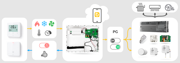
All logic and settings are held directly in the periphery
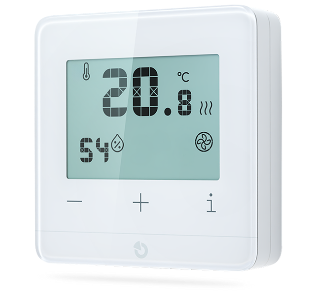
The JB-111TP, JB-151TP, JB-111TH and JA-151TH system thermostats measure room temperature, relative humidity and, if necessary, floor temperature. They store settings made locally and remotely by the user directly in their internal memory.
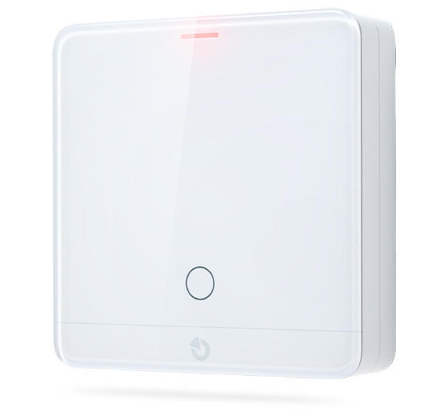
 JB-111TP
Bus room thermostat
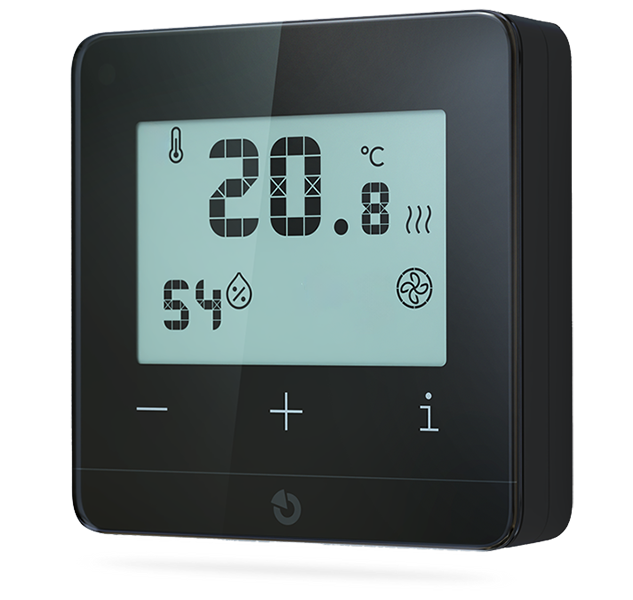
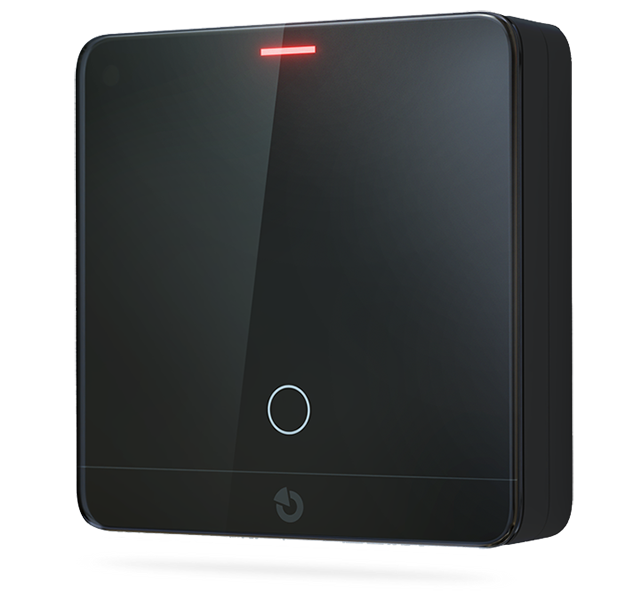
 JB-111TP-AN
Bus room thermostat - anthracite
 JB-151TP
Wireless room thermostat
 JB-151TP-AN
Wireless room thermostat - anthracite
 JB-111TH
Bus temperature and humidity sensor with thermostat function
 JB-111TH-AN
Bus temperature and humidity sensor with thermostat function - anthracite
 JB-151TH
Wireless temperature and humidity sensor with thermostat
 JB-151TH-AN
Wireless temperature and humidity sensor with thermostat - anthracite
Based on a comparison of the measured and currently required values, they send commands to the control unit to switch on and off the PG outputs assigned to the individual heating, cooling and ventilation modes.
The thermostats work together with the control unit. Based on security settings, they automatically shorten the comfort period in the temperature schedule. Based on the blocking of the PG output, they automatically stop heating when it is not needed, for example when a window is open or when there has been no movement in the room for a long time. These unique features significantly reduce the operating costs of the heating system.
The control unit serves as a distribution centre
The system control unit mediates two-way remote communication with the user and transmits user settings and control instructions to individual thermostats. In doing so, it provides the thermostat with the necessary information about events in the system.
In the opposite direction, the control unit receives commands from the thermostats and compares them with the set blocking conditions. The result is the switching on and off of individual PG outputs, which the control unit transmits via the bus or radio to the system.
The control unit also provides backup power to the bus thermostats.
Output peripherals switch connected appliances
Whether it is a complex unit for regulating underfloor heating, a separate valve head, a smart socket or a universal relay, the output elements simply copy the status of the assigned PG outputs. Based on this, they supply and remove power to the connected appliance or open and close the radiator valve.
This solution makes the entire system highly flexible and allows it to be connected via bus or wirelessly to a wide range of appliances without the need for any related construction work. Smart and economic zone control can therefore be added retrospectively in situations where it was not originally planned.
System limits
The number of thermostats in the system is limited only by the number of unoccupied peripherals. However, the limits of wireless transmission must be considered:
- Wireless peripherals can only be programmed into the system in positions 1 to 120.
- Only PG outputs in positions 1 to 32 can be transmitted wirelessly.
Most common applications
The flexibility described above allows for a variety of applications to be implemented, depending on the specific needs of the customer and the possibilities of the building where the system is installed. For simplicity, we will summarise the three most common methods.
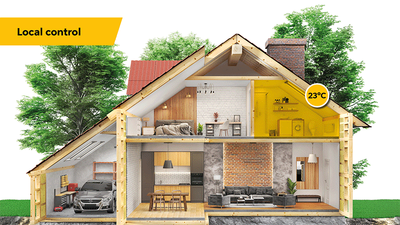
Local control
This refers to situations where the JABLOTRON system is needed to cover a smaller space. Typically, this is the case if the space was added later or is part of a larger building where the existing heating and ventilation solution is insufficient, or if remote temperature control is needed in that location. In these cases, it is usually a fully wireless solution, where one thermostat controls a separate, often electric, heat source, fan or dryer. For example:
- A bathroom in an older flat with a retrofitted electric heated towel rail and extractor fan, the automation of which will help prevent problematic drying out and mould growth.
- A cottage with an additional electric heater, which the thermostat not only uses to regulate the temperature, but also allows the user to remotely heat the cottage long before arrival and lighting the stove.
- A garden shed or detached garage, where the thermostat uses a direct heater to maintain a safe temperature, etc.
Central control
A common solution, typical for older family homes and similar buildings. A limited number of thermostats, located at reference points (e.g. the living room and upstairs hallway), control a single common heat source, typically a gas or electric boiler.
In this case, the entire building is heated if at least one of the installed thermostats requires it. Heat from the boiler is distributed to individual radiators or underfloor heating. The temperature in individual rooms is then regulated manually using mechanical heads or, less conveniently, by opening a window.
This solution, which focuses on low acquisition costs, usually means high long-term operating costs. To reduce these costs, the system can be easily expanded with more wireless thermostats and valve heads to ensure at least partial zone control in rooms where heating is not needed all the time.
Zone control
A modern solution that minimises long-term operating costs while maintaining the necessary comfort. For zone control, each room is equipped with its own thermostat, which maintains the desired temperature locally by controlling a specific radiator, underfloor loop or electric heater.
Thanks to the division of control into individual zones, different rooms can be heated at different times to different temperatures. This significantly reduces heat waste when the room in question is not in use. The temperature in the room is controlled according to a set schedule so that it is only heated to a comfortable level at specific times, typically:
- In the living room on weekdays in the afternoon and evening, and all day at weekends
- In the bathroom in the morning and evening every day
- In the bedroom only in the morning every day
- In children's rooms on weekdays in the morning and afternoon, and all day on weekends
With hot water zone control, thermostats control not only individual rooms but also the boiler or heat pump, as with central control. However, by using heat only in selected rooms, the source operates for a shorter time and at a lower output, resulting in significant savings.
Construction preparation for thermostats
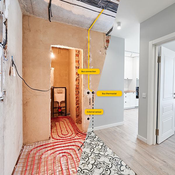
Wireless thermostats can be installed in any location, even retroactively. However, if it is possible to install cabling in the building, we always recommend using bus peripherals for long-term maintenance-free operation, lower acquisition costs and other advantages. For bus thermostats, it is necessary to select the correct location in advance where the bus cabling will terminate.
The general recommendations for placement also apply to JABLOTRON thermostats:
- Installation height 120 to 150 cm
- A place where there is no direct sunlight that could affect the measurements
- A location away from windows, which could affect measurements if left open or leaking
- A place that is easily accessible to the user and where there is no risk of future obstruction by furniture
Simply put, a suitable location is usually above the light switches at the entrance to the room, with the ideal height of the thermostat axis being 30 cm above the axis of the switches. Run the prepared cabling to a flush-mounted installation box with a screw spacing of 60 mm, into which the bus thermostats can be conveniently partially recessed.
If for some reason it is not possible to recess the box, the thermostat can also be surface-mounted. In this case, lead the cabling out of the plaster in the centre of the planned location of the product. The cabling must reach this location from above or below so that it is not damaged during drilling during installation (the installation holes are located horizontally).
Preparation for the floor sensor:
Run a flexible protective sleeve with a diameter of 15 to 20 mm from the installation box for the thermostat to the floor. The protective sleeve should end at the same height as the floor structure in which the heating itself will be laid.
The end of the protective sleeve, i.e. the place where the measuring sensor will be located, should be at least 30 to 50 cm from the wall, in the middle between the floor heating loops, so that it is not too close to the pipe or cable. Seal the end of the protective sleeve against dirt or screed ingress.
If the heating is yet to be laid, bring the protective sleeve out of the wall at a suitable height (approx. 4 cm below the planned zero level, or rather lower than higher) and leave a sufficiently long excess, e.g. 1.5 m. Mark the protective sleeve; the heating engineer will take care of its final trimming and placement.
The sensor itself is installed at the time of final thermostat installation by simply inserting it into the protective sleeve until it stops.
Bus cabling distribution:
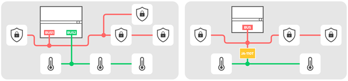
The bus for thermostats can be routed in series, tree or star configuration, as with other bus peripherals. The end of the branch must always terminate at the last peripheral or be freely insulated against short circuits. A closed loop must never be created on the bus.
Thermostats, as non-security peripherals, are not protected by a tamper contact. To meet the requirements for Security Grade 2, they must be connected separately so that in the event of thermostat tampering and bus short-circuiting, the functionality of the alarm elements is not compromised.
In practice, a combination of series and star wiring can be used, where all non-security elements are connected in series on several branches, diverging in different directions for effective coverage of the entire building. These branches are then connected to a single common JA-110T isolator or a single dedicated bus output of the control panel. The alarm elements must be connected to the second output or branch off from the node before the isolator.
Connecting JABLOTRON 100+ to specific appliances
Hot water underfloor heating
The most common solution in modern family homes, allowing for a variable choice of heat source.
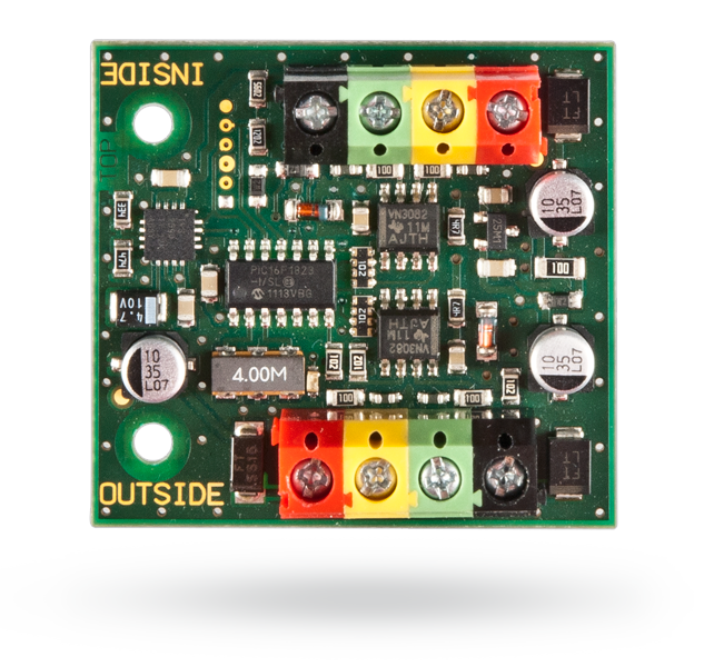
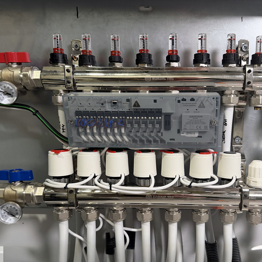
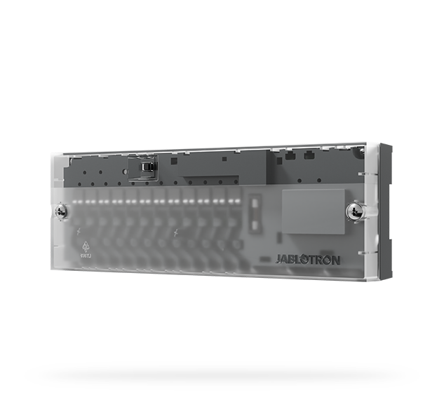
To regulate it, use the JB-128N modules, which can independently control up to 12 zone heating circuits. Individual outputs for floor heads are simply assigned to PG outputs, controlled by individual thermostats when heating is required. At the same time, the module can also automatically switch the heat source and auxiliary pump, ensuring the circulation of heating water. A single product can thus easily cover the control of the entire house.
What you will need:
- Thermostats with floor sensors installed in individual rooms.
- Suitable NC 230 V thermoelectric heads with a maximum power consumption of 2 W. You can consult or directly ask the supplier of the heating system in the building for the specific type compatible with the manifold in question.
- During testing, we found the T30NC heads from Salus to be particularly effective. In addition to electrical properties, the correct size and thread pitch for mounting on the manifold valves are crucial.
- Module for controlling hot water underfloor heating JB-128N.
- In cases where it is not possible to connect the JB-128N module to the central heat source via cable, a suitable universal relay can also be used, see point 5.
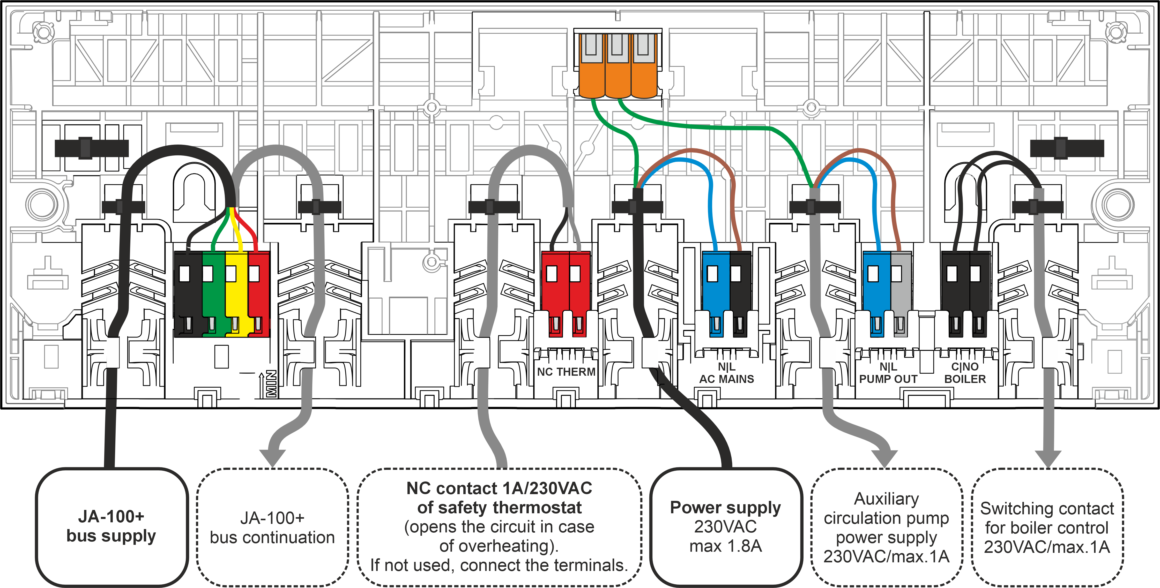
Electrical preparation for JB-128N:
- The module can be installed in a floor manifold by attaching it directly to the pipes with tape, or alternatively next on a DIN rail or flat surface.
- The module must be connected to the system via a bus using a suitable cable with at least two twisted pairs. CC-01 or CC-02 cables from the JABLOTRON portfolio are ideal, but universal cables such as SYKFY, UTP, etc. are also acceptable.
- The module also requires a constant power supply from a 230 V mains supply. The ideal setup is a CYKY-J 3x1.5 cable between the floor distributor and the electrical switchboard, with a circuit fuse of 4 to 10 A.
- Optionally, the module can be used to control a heat source, such as a gas/electric boiler or heat pump. The module switches on a potential-free output if at least one circuit is heating. The output load capacity is up to 1 A at 230 V AC or 30 V DC.
- The control terminals of the appliance are usually potential-free, with the logic connected to GND = heating, disconnected from GND = no heating, so a weaker cable is usually sufficient for control. However, to be sufficiently prepared for the future, we recommend preparing a CYKY-J 3x1.5 cable between the distributor and the heating source for control.
- If cable preparation is not possible, the heat source can also be controlled by any output module from the JABLOTRON portfolio, see point 5.
- Optionally, you can also use the module to power an auxiliary circulation pump, which switches on automatically when at least one circuit is heating.
- If the pump is part of the manifold, it can be connected directly to the module. Otherwise, prepare a CYKY-J 3x1.5 cable between the manifold and the pump.
- If cable preparation is not possible, the pump can also be switched by any output module from the JABLOTRON portfolio. The function can be set in the software, see heat source.
- The pump can also be controlled directly by the heat source (provided by the heating system supplier).
- A safety NC thermostat can also be connected to the module, which will open when the heating water temperature at the manifold inlet reaches a dangerously high level. The individual outputs of the module are powered via the safety thermostat, so the load capacity of the thermostat contacts must be at least 230 V AC 1 A. If the thermostat is not connected, the terminals on the module must be permanently connected.
- If the thermostat is installed directly in the manifold, it can be connected directly to the module. Otherwise, prepare a CYKY-J 5x1.5 cable between the two appliances, which can also be used to power the circulation pump if it is located near the thermostat.
Electric underfloor heating
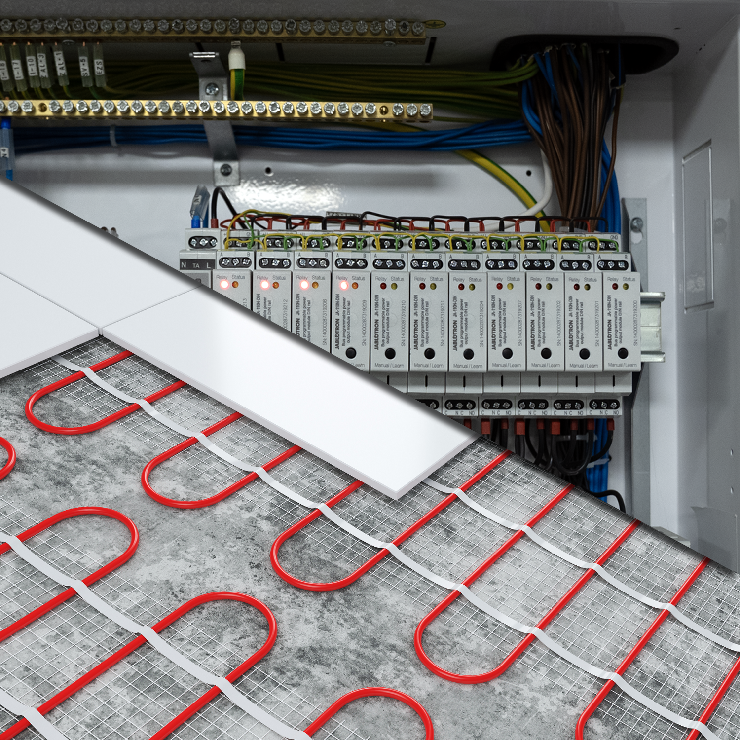
This solution is particularly popular in passive and low-energy houses. It is popular in wooden buildings with minimal thermal inertia (they heat up quickly and cool down quickly). Zone electric heating and the flexibility of JABLOTRON control are extremely advantageous here thanks to their ability to respond quickly to user needs based on alarm events.
Resistance heating cables, mats or foils are used for electric underfloor heating, embedded directly in the screed layer or in the structure just below the floor covering. Heating circuits are usually implemented individually for each room. In large rooms, such as a living room connected to a kitchen, the space can be divided into several separate circuits.
Each circuit has its own cable power supply, usually leading to a box above the floor in each room, where it connects to the electrical wiring. Ideally, each circuit has a separate supply from the distribution board, but alternatively, multiple heating circuits can be connected to a single power branch.
The power consumption of individual circuits ranges from a few hundred watts to 3.6 kW, depending on the size of the room, its design heat loss and the required heating speed. For low-energy buildings, a power consumption of up to 1 kW can be expected for standard living spaces up to 15 m².
What you will need:
- Thermostats with floor sensors installed in individual rooms.
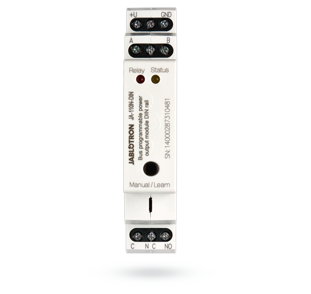
- Power relay modules in numbers according to individual heating circuits
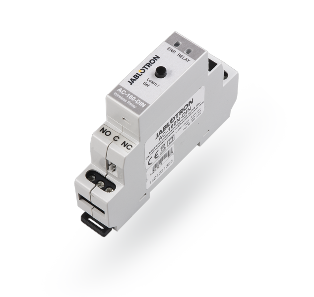
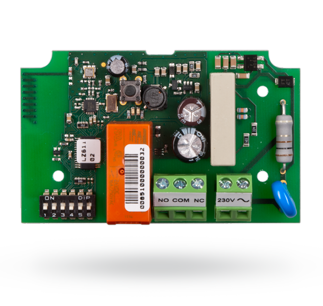
- Installation in a switchboard: JA-110N-DIN or AC-160-DIN
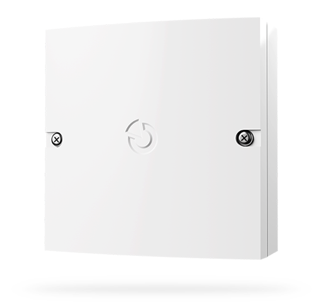
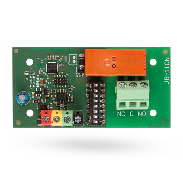
- Installation on the circuit supply, powered from a common branch: If the supply is terminated in a deep box, the AC-160-C wireless relay can be used. If there is not enough space in the box, the JA-190PL box with the JA-150N wireless module or the JB-110N bus module can be installed on it.
Electrical preparation for electric underfloor heating:
- Agree on the location of the supply for the heating circuit with the customer and the heating supplier. We recommend using a deep installation box in which the fixed supply can be conveniently connected to the usually flexible power cable of the heating circuit. The connection should be accessible for inspection and any subsequent modifications to the system.
- Ideally, run a separate CYKY-J 3x2.5 power cable from the switchboard for each heating circuit separately. This solution is elegant both aesthetically (the relays are hidden in the switchboard) and in terms of subsequent installation comfort and electrical safety. Allow sufficient space in the switchboard for individual relays and a reserve for further system development.
- If it is not possible to run separate power supply lines, but a common branch is used for multiple heating circuits, switching must be carried out at individual branches. Although this solution is more economical in terms of cable consumption, it requires more complex installation of relay modules outside the switchboard and careful calculation of individual circuits to ensure that the circuit protection value is not exceeded when switched on together.
Radiator heating
If the necessary comprehensive cable preparation can be carried out, the JB-128N module can also be used for radiators. In this case, the module can be installed, for example, in an electrical switchboard, and the individual heads are installed directly on the radiators instead of the manifold; otherwise, the solution is the same as in point 1.
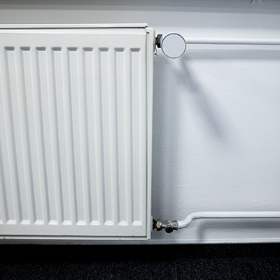
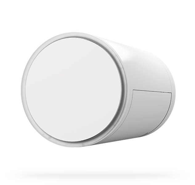
However, when controlling radiators, which are typical in older houses and flats, it is more common to install them retrospectively when it is no longer possible to run cabling throughout the building. In this case, it is ideal to use JB-150N-HEAD wireless valve heads. Their advantage is that they are easy to install without any construction preparation or disruption to the interior. The three AA alkaline batteries in the head last the entire heating season and can be replaced by the user.
If there are multiple radiators in the room, one thermostat can control several heads that copy the common PG output.
The radiator valve itself must operate smoothly. In the case of older radiators, first check with the manual head that the valve is not stuck or that there are no moments of significantly higher resistance during operation. In this case, we recommend replacing the valve body itself with a new one first.
What you will need:
- Thermostats installed in individual rooms or reference points.
- JB-150N-HEAD heads according to the number of radiators controlled. The package includes an adapter for the most used valves with M30 x 1.5 threads. Separately sold adapters JB-VA16, JB-VA26, JB-VA78 and JB-VA80 are also available for alternative radiator valves.
- If, in addition to radiators, the heat source itself (e.g. boiler) needs to be controlled in the building, then a suitable universal relay is also required, see point 5.
Electric heaters
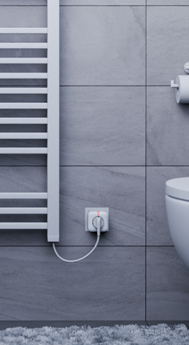
A popular solution for bathroom heated towel rails or portable heat sources for additional or supplementary heating. Whether you need to prevent mould and dry towels, heat a garden shed or remotely control the temperature in your cottage, the advantage of electric heaters is that they can be put into operation immediately anywhere, without connection to a central heat source.
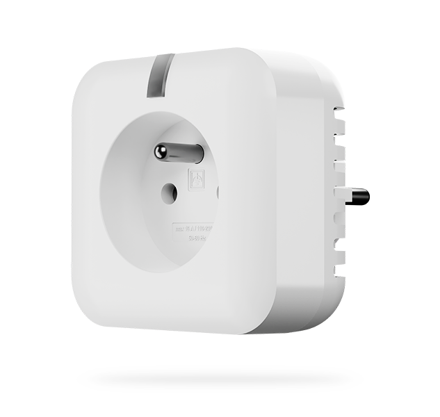
The JB-164N-PLUG / JB-165N-PLUG switched socket with consumption measurement is therefore ideal for controlling electric heaters. It not only provides the same flexibility for placement and installation, but also an overview of how the operation of the appliance affects the operating costs of the building. Thanks to its robust construction, the plug-in adapter can safely switch up to 16 A (3,600 W) at 230 V AC.
The socket is simply assigned a PG output controlled by a thermostat; when the thermostat is heating, the socket allows current to flow to the appliance and vice versa. It is necessary to verify that the electric heater allows operation controlled by connecting and disconnecting the power supply (some appliances may require manual start-up on the digital control after the power supply is connected). If there are multiple direct heaters in one room, one thermostat can control several of them together (the sockets will copy the same PG output).
What you will need:
- Thermostats installed in individual rooms or reference points, depending on the location of the individual direct heaters. Wireless thermostats can remain mobile; simply place them on a shelf, for example.
- JB-164N-PLUG / JB-165N-PLUG sockets, depending on the number of appliances to be switched.
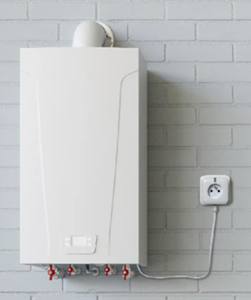
Central heat source
For central heating control, or even zone hot water heating control, it is also necessary to control the heat source, such as a gas or electric boiler or an indoor heat pump unit.
Most of these appliances are equipped with a universal pair of terminals for an external thermostat. The terminals are usually volt-free and have a simple function: when connected, the appliance heats, when disconnected, it does not. Consult the appliance supplier about the connection or follow the installation instructions.
If you are implementing zone hot water underfloor heating with the JB-128N modules, you can use the module output designed for controlling the heat source, see point 1. In other cases, you can use any relay module from the JABLOTRON range of output modules.
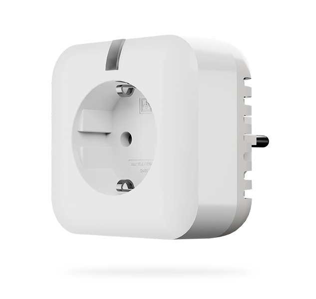
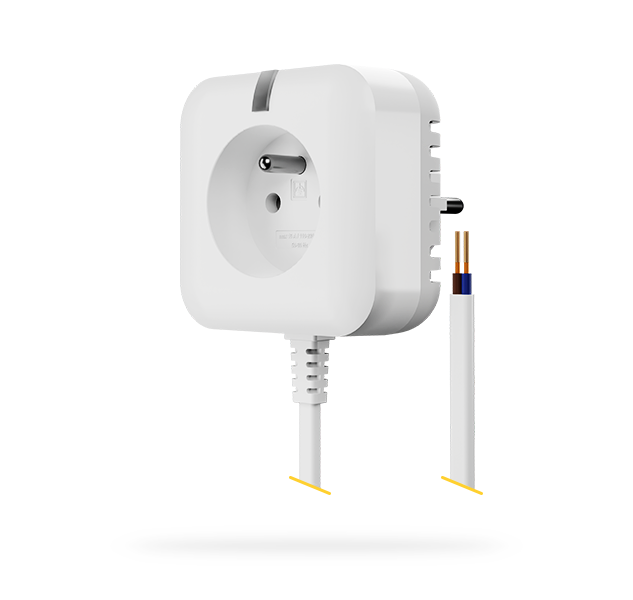
However, the JB-162N-PLUG / JB-163N-PLUG socket allows for the simplest application in this case.
The socket itself is permanently energised, with a volt-free NO contact connected to the cable. It can be easily plugged into a socket designed for an appliance and the control cable can be routed along the appliance's power cable to the control terminals for the thermostat.
In the settings, simply assign the PG that the socket copies by switching the cable output when heating is required. This solution does not require any construction preparation other than the availability of a power socket and is therefore extremely suitable for retrofitting.
PG connection settings
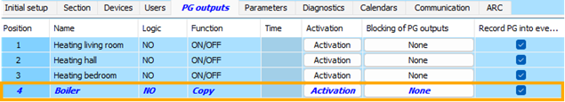
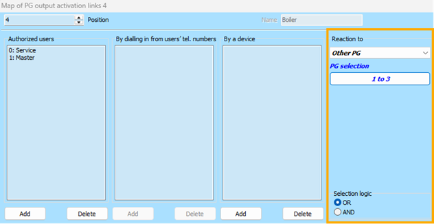
- If you use the JB-128N module to switch the heat source, there is no need to set any links; the module controls the heat source automatically according to the status of the individual circuits.
- If there is only one thermostat in the system, it will simply control the PG, which will also copy the relay switching the heat source.
- However, if there are multiple thermostats and they share a single heat source, switched by one of the universal output modules, it is necessary to create a separate PG output for the heat source, which will use “OR” logic to copy the PG outputs of the individual thermostats: if at least one of the thermostats is heating, the central heat source will also heat.